
Abstract: The attached drawings of specification may be used as the basis for the amendments of the application documents. However, when the application documents are modified according to the attached drawings of specification, both the literal parts of the original specification and claims and the contents that can be determined by the attached drawings should be judged as a whole, assuring the technical information in the amended application documents be consistent with the technical information recorded in the original application documents so as to avoid amendments going beyond the scope of the original specification and claims.
Chinese Patent Law allows the applicant to amend the patent application documents while strictly restricting the content of the amendments.
As set forth in Article 33 of the Chinese Patent Law, “an applicant may amend his or its patent application for a patent, but the amendment to the application for a patent for invention or utility model may not go beyond the scope of the original disclosure contained in the initial description and claims”.
As specified in section 5.2.1.1, Chapter 4, Part II of Guidelines for Patent Examination(2010), the scope of disclosure contained in the initial description and claims includes the contents described in the initial description and claims, and the contents determined directly and unambiguously according to the contents described in the original description and claims and the drawings of the description.
Therefore, the contents shown in the attached drawings of specification can fully serve as the basis for the modification of the application documents. In practice, however, how to judge whether the contents of the revised application documents based on the drawings go beyond the scope of the initial description and claims, has become a sensitive and hot issue.
Hereinafter, the author’s thoughts and considerations on avoiding amendments based on the drawings going beyond the scope of the initial disclosure would be addressed detailedly with typical cases.
1. Information of the Cases
(1) Case 1
The patent involved is an invention patent ZL02127848.2 entitled “rear shifting device” which is granted by the National Intellectual Property Administration of PRC(hereinafter referred to as CNIPA) on August 30 in 2006, with the application date of February 3 in 1994 and the priority date of February 3 in 1993 . The patentee of the invention patent is SHIMANO KK [JP] (hereinafter referred to as SHIMANO). Actually, the patent involved is a divisional application of a original application No. 94102612.4 named “rear derailleur bracket”, with the priority date of February 3 in 1993 and the publication date of December 7 in 1994, filed by SHIMANO with CNIPA.
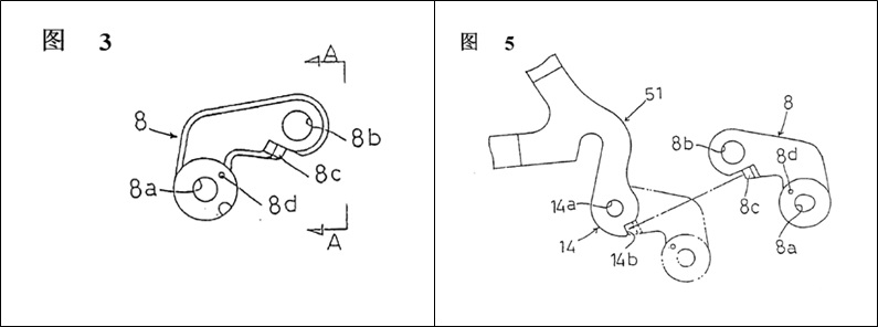
In the specification of original application, “the first connecting means and the second connecting means being in form of substantially circular bolt bores” is recorded in last line of page 2 to line 1 of page 3; “the bracket 8 includes a first circular bolt bore 8a disposed adjacent one end thereof, and a second circular bolt bore 8b disposed adjacent the other end” is recorded in Lines 1-2 from the bottom of page 4; “bolt bores 8a” or “bolt bores 8b” are recorded in Lines 1,6,10,11,21 of page 5 and lines 2,5 of page 7; “the bolt bores 8a and 8b of the bracket 8 may be replaced by devices having various others shapes” is recorded in Lines 5-7 of page 7. Figures 3, 5 attached to the original application clearly show that the first connecting means and the second connecting means 8a and 8b are roughly circular bores.
Based on above contents, SHIMANO amended the divisional application. One of the main amendments is to generalize “substantially circular bolt bore”, “circular bolt bore” or “bolt bore” involved in claim 1, 3 and 6 as “circular bore”. Revised claims 1, 3 and 6 for the patent involved are as follows:
A rear derailleur(100), including: bracket member(5); support member(4) for supporting the chain guide(3) having a guide wheel(1) and a tension wheel(2); a pair of right and left pivot links(6,7) for interconnecting the support member(4) and bracket member(5); bracket(8) that contains a first connecting means(8a), a second connecting means(8b) and the positioning means(8c), wherein the first connecting means(8a) is located near one end of the bracket(8), so that the bracket member(5) is connected to the bracket(8) and pivotable about a first axis(91), and the second connecting means(8b) is located near the other end of the bracket(8); a tension spring(12) mounted in the bracket member(5); which is characterized in that the bracket(8) is formed of an approximately L-shaped plate; the second connecting means(8b) of the bracket(8) is in the shape of a roughly circular bore; the bracket(8) has a bore(8d) formed adjacent to the first connecting means(8a), for receiving one end of the tension spring(12) to connect the first tension(12) to the bracket(8); shape of the positioning means(8c) is a stepped projection extending from surface of the plate and being positioned adjacent to the second connecting means(8b).
The rear derailleur(100) according to claim 1, characterized in that the first connecting means is in the form of a roughly circular bore(8a) .
The rear derailleur(100) according to claim 1, characterized in that the roughly circular bore(8b) is arranged to allow a connecting bolt (16) to pass through.
In response to the above amendments, Ningbo Saiguan Vehicle Industry Co, Ltd. (hereinafter referred to as Saiguan Company) has twice filed a request for invalidation with the Patent Reexamination Board of CNIPA (hereinafter referred to as PRB), based on the invalidation reasons that such amendments goes beyond the original disclosure, which is not in conformity with Article 33 of the Patent Law.
PRB asserts that, the circular bore is the upper concept of “substantially circular bolt hole”, “circular bolt bore”, and the technical meaning thereof is different from “bolt bore”. Although reference numerals 8a,8b show circular bores, the circular shape shown in the drawings should be understood as for just briefly showing the shape of the “substantially circular bolt hole”, “circular bolt bore” or “bolt bore”, since the role of the drawings is to make people able to intuitively, vividly understand the technical solutions, to explain the technical solutions. It cannot be assumed that "circular bore" and “substantially circular bolt hole”, “circular bolt bore” or "bolt bore" have the same technical meaning as “circular bore” just because the bore shown in the drawing is circular. Therefore, the generalization of “substantially circular bolt hole”, “circular bolt bore” or "bolt bore" to “circular bore” goes beyond the scope of the original specification and claims, and does not comply with the provisions of Article 33 of the Patent Law.
PRB declared all the patents involved invalid. SHIMANO refused to accept the invalidation decision and filed an administrative lawsuit with the Beijing NO.1 Intermediate People’s Court. The Beijing NO.1 Intermediate People’s Court held the decision of the Patent Reexamination Board in the first instance. SHIMANO refused to accept the first-instance judgment and appealed to the Beijing Higher People’s Court. The second instance of the Beijing Higher People's Court upheld the first-instance judgment of the Beijing No. 1 Intermediate People's Court and the decision of the Patent Reexamination Board. SHIMANO refused to accept the second-instance judgment and applied retrial to the Supreme People's Court of the People's Court.
The Supreme People’s Court of the People’s Republic of China forms a collegial panel to conduct a public hearing. During the retrial, SHIMANO considered that the first and the second connecting means 8a,8b are generally circular bores clearly shown in the Figures 3, 5 of the original application. It is also mentioned in the lines 5-8 of page 7 of the specification that the bolt bores can be replaced by other kinds of devices, that is, 8a and 8b are not limited to the bolt bores. Bolt bores refer to "bores used for bolt penetration", rather than "bores with screw threads". In the patent involved, there is no difference between "circular bores" and "circular bolt bores" in structure and function. Therefore, the generalization of “substantially circular bolt hole”, “circular bolt bore” or "bolt bore" to a circular bore is not beyond the scope of the original specification and claims, and complies with the provisions of Article 33 of the Patent Law.
The collegial panel of PRB held that in the original application text, 8a and 8b were essentially defined by two technical features, one is the circular bore, the other is for the bolt to pass through. In the patent claims 1, 3, SHIMANO has changed “substantially circular bolt hole”, “circular bolt bore” or "bolt hole" to “circular bore”, and deleted the technical features of “for the bolt to pass though”, the rest of the patent claims 1, 3 did not show the technical information that 8a and 8b can only be used for the bolt to pass through. In fact, in mechanical field, for circular bores, it can also allow pins and other connecting parts pass through. For ordinary technicians in this field, "circular bore" and "circular bolt bore" have different technical meanings. The above modification of SHIMANO does not belong to the content that can be determined from the original application. Therefore, the modification of the patent claims 1, 3 involved in the case goes beyond the scope of the original specification and claims, and does not comply with the provisions of Article 33 of the Patent Law. Claim 6 clearly defines 8b by additional technical features as a circular bore through which the connecting bolt may pass. This modification does not cause the technical information that the person skilled in the art sees on 8b to differ from the technical information disclosed in the original application text, so it does not go beyond the scope of the original specification and claims, and conforms to the provisions of Article 33 of the Patent Law.
(2) Case 2
The patent involved is named "a precision feed turning tool holder", filed on March 14, 2003 with the application number 03111166.1. The applicant is DaLian XinGuang CNC Machinery Co., LTD in Dalian Economic And Technological Development Zone.
During the substantive examination stage, the substantive examination department of CNIPA issued a rejection decision on the submitted application documents. The rejected independent claim 1 is as follows:
“ A precision feed turning tool holder characterized in that the turning tool holder is composed of:
--shell (1);
--excitation coil (2) placed in the shell (1);
--magnetostrictive rod (3) placed in the excitation coil (2);
--a spring plate (4) disposed at an end of the shell (1) and having one end fixed to the shell(1) and one side thereof forming active contact with the magnetostrictive rod (3);
--a turning tool holder (6) placed on the other side of the spring plate (4).”
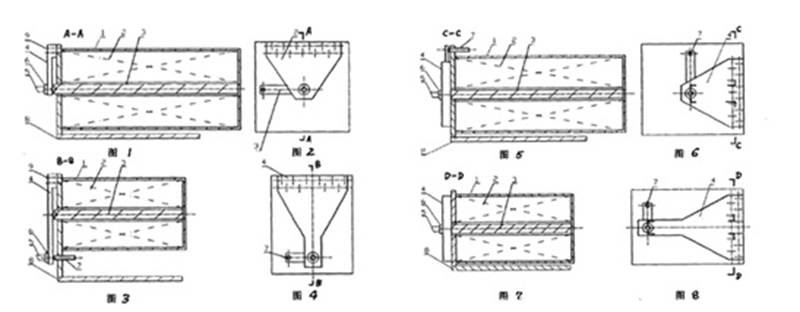
In response to the above rejection decision, the applicant (hereafter referred to as the reexamination requester) filed a reexamination request with the PRB and amended the application documents. The amendments to the application documents are mainly based on the drawings attached to the specification. The attached drawings of original specification of the patent involved are as follows:
Independent claim 1 as amended by the review requester is as follows:
“A precision feed turning tool holder, which is characterized in that the holder is composed of the following structures: shell (1), excitation coil (2), magnetostrictive rod (3), spring plate (4), turning tool holder (6); wherein the excitation coil (2) is placed in the shell (1), and the magnetostrictive rod (3) is placed in the excitation coil (2); the spring plate (4) has a triangular shape, the spring plate (4) is placed at the end of the shell (1), and the large end of the spring plate (4) is fixed to the shell (1), and the other end is suspended and one side thereof is forming active contact with the magnetostrictive rod (3); the turning tool holder (6) is placed on the other side of the spring plate (4) away from the magnetostrictive rod (3). ”
PRB established a collegial panel in accordance with the law to deal with the case. The collegial panel believes that the reexamination requester's amendments to the application document mainly adds the following technical features, such as "the shape of the spring plate is triangular", "the large end of the spring plate is fixed to the shell, the other end is suspended", "the turning tool holder is placed on the other side of the spring plate away from the magnetostrictive rod" to the claim 1. It is considered that, "(spring plate) may have a triangle shape that may be equal in thickness or unequal in thickness," is recorded in paragraph 5 of page 2 of the original specification, and therefore the shape of the spring plate is further amended with limitation "triangle" in the claims, which complies with the provisions of Article 33 of the Patent Law. In paragraph 6 of page 2 of the original specification, the relationship between the displacement of turning tool 5 and the expansion of the magnetostrictive rod 3 are described, when the turning tool holder 6 and the turning tool 5 are in different positions on the spring plate 4, relative to the fixed end 9 of the spring plate 4 and the apex of the magnetostrictive rod 3. Further referring to the drawings, Figures 1 and 2 clearly show that the one end of the spring plate 4 having a larger width is fixed to the shell 1, the middle portion of the spring plate 4 having a smaller width actively contacts with the apex of the magnetostrictive rod 3, the other end of the spring plate 4 having the smallest width is freely suspended, and the turning tool holder 6 is located on the other side of the spring plate 4 opposite to the magnetostrictive rod 3; In Figs. 5-8, only the fixing positions of the spring plate 4 and the shell 1 are changed, but the lever type mounting structure of the spring plate 4 is not changed. Thereby, combining the above-mentioned literal parts and the drawings in the specification (especially Figures 1-4), the mounting structure of the spring plate can be directly and unambiguously determined as: the fixed end of the spring plate (i.e. the large end) is fixed to the shell, and the other end is free (suspended), the apex of the magnetostrictive rod is in active contact with one side of the spring plate to form a support end, and the turning tool holder is located on the other side of the spring plate opposite to the magnetostrictive rod. Therefore, according to the contents of the original specification and the drawings of the specification, the amendments made by the reexamination requester to the application documents can be directly and unambiguously determined without going beyond the scope of the original specification and the claims, and thus the amended application documents comply with Article 33 of the Patent Law.
2. Case Comments
As for the above case 1 and case 2, when the application documents are modified, the drawings of specification are used as the basis for modification to the claims. However, the results of judgments about whether the amendments go beyond the original disclosure are totally different.
In the author's opinion, the reasons why there are two totally different judgment results in case 1 and case 2 are as follows:
The drawings of the specification, as an integral part of the specification, are not isolated and thereby necessarily related to the features described in the text of the specification. When amending the application documents based on the drawings of the specification, the text and the drawings of the specification should be combined as a whole to understand. The features visually seen in the drawings of the specification cannot be separately converted into words without paying attention to the contents of the specification. Amending the application documents separately according to the features visually displayed in the drawings of the specification may easily cause the technical information recorded in the amended application documents to be inconsistent with the technical information recorded in the original application documents, thereby resulting in the defect of amendments going beyond the original disclosure.
In case 1, although it can be clearly seen that the shapes of 8a and 8b are substantially circular in the drawings, SHIMANO KK [JP] ignored the information in the text of the specification. The shape of 8a and 8b described in the specification not only satisfies the circular shape, but also satisfies the characteristics that the bolt can pass through. SHIMANO KK [JP] changed “substantially circular bolt hole”, “circular bolt bore” or “bolt bore” to “circular bore” in claims 1, 3, and deleted the technical features of “for the bolt to pass though”. As a result, this amendment leads to a situation in that the technical information recorded in the revised claim is inconsistent with the technical information recorded in the original application document. Therefore, the final judgment to claim 1 is that the modification goes beyond the scope of the original specification and claim. While additional technical features in claim 6 clearly define 8b as the circular bore through which the connecting bolt passes. The technical information recorded in the revised claim is consistent with the technical information recorded in the original application document. Therefore, the final judgment to claim 6 is that the modification does not go beyond the scope of the original specification and claim.
In addition, the drawings of the specification serve as an important part of the specification, and have an auxiliary understanding function for the text of the specification. When amending the application documents based on the drawings of the specification, the drawings of the specification can be used as an auxiliary tool to refine the technical content described in the specification or to change the literal description of technical feature, in order to ensure that the technical information recorded in the modified application document is consistent with the technical information recorded in the original application document, and to avoid the modification going beyond the scope of the original disclosure.
The description of case 2 records that the shape of the spring plate may be a triangle of equal or unequal thickness, and the structure of the frame is generally summarized as a lever-type mounting structure by different embodiments. The drawings of specification including the longitudinal section of the vehicle frame and the structural view of the end face can clearly reflect that the lever-type mounting structure of the spring plate is: the fixed end of the spring plate (i.e. the large end) is fixed to the shell, and the other end is a free end (suspended), the apex of the magnetostrictive rod is in active contact with one side of the spring plate to form a support end, and the turning tool holder is located on the other side of the spring plate opposite to the magnetostrictive rod. Therefore, the applicant of the case 2 refines the technical features involved in the original claims and changes the expression, adding the following technical features "the shape of the spring plate is triangular", "the large end of the spring plate is fixed to the shell, the other end is suspended", and "the turning tool holder is placed on the other side of the spring plate away from the magnetostrictive rod" to the claim, which only improve the literal description for the information recorded in the original application documents. The technical information described in the revised claims is identical to the technical information described in the original application documents, and the amendment basis and reasons for the modification not gong beyond the scope of the original disclosure are fully explained. Therefore, the final judgment is that the modification does not go beyond the scope of the original specification and claim.
In conclusion, when the application documents are to be modified according to the attached drawings of specification, both the literal parts of the original specification and claims and the contents which can be determined by the drawings attached to the original specification should be judged as a whole. Furthermore, the drawings of the specification can be used as an auxiliary tool to refine the technical content described in the specification or to change the description of technical feature, but it should also be noted whether the technical information recorded in the revised application documents is consistent with the technical information recorded in the original application documents, so as to avoid the modification going beyond the scope of the original specification and claims.