
Abstract: When common terminology is used to describe the technical characteristic in patent document, how to understand and interpret the technical characteristic becomes the key to judge the validity of the patent. For the technical characteristic described by common terminology, the interpretation thereof should include the structure and properties contained in the known definition of the common terminology. For the technical characteristics described by common terminology, although the common terminology itself is familiar to those skilled in the art, it does not mean that the application of the technical characteristics in the specific technical solution of the patent belongs to public knowledge. For the patent which first puts forward a new idea of using a known part to solve specific technical problems, defining the known part by the common terminology is beneficial for the patentee to control the disclosure content and retain the technical knowhow to a certain extent.
For the judgment of patent validity during substantive examination and invalidation request examination, the parties inevitably understand and interpret the technical features in the technical solutions of the Specification and Claims. Moreover, the understanding and interpretation of such technical features often become the key to determine the validity of the related patents.
In practice, the words used to describe the technical feature are often diverse. Moreover, although it is allowed to define technical terms as per Chinese patent practice, it is more common to use the common terminology in the field. As specified in Section 3.2.2, Chapter 2, Part II of the Guidelines for Patent Examination (2010), “the extent of protection of a claim shall be construed according to the meaning of the words used in the claim. Generally, the words used in a claim shall be understood as having the meaning that they normally have in the relevant art.”
When the invention spirit of patent utilize a known element in the art and a common terminology in the field is used to describe the corresponding technical characteristics, how should the common terminology be considered in judging the validity of the patent, especially referring to the disclosure completeness of the Specification and inventiveness of the patent?
Hereinafter, the author’s thoughts and considerations would be addressed detailedly with typical cases.
1. Introduction of the Case
As one of the top ten cases of patent reexamination and invalidation in 2016, this case is an invalidation request of Utility Model Patent (hereinafter referred to as “the patent”) with a title of “ novel photographic guide rail ”.
(1) Basic Information of the Case
The Date of Request of Invalidation: Mar. 2, 2016
The Invalidation Case No.: 29889
Title of the Invention: novel photographic guide rail
Patent Application No.: 201320578735.3
Filing date: Oct. 21, 2014
The Patentee: Zhongshan dashan photographic equipment co., LTD
Requester of Invalidation: Huizhou latu photographic equipment co., LTD
Invalidation Reasons: The patent does not comply with Article 22.3, 26.3 and 26.4 of the Patent Law
Invalidation Evidence 1: CN202522832U
Examination Decision: Maintaining the validity of the patent
(2) The Patent
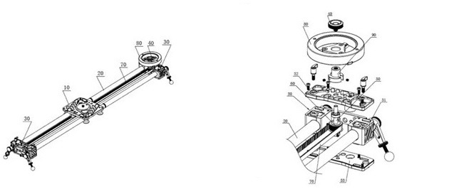
FIG.1 of the patent FIG.3 of the patent
As described in the Background Technique of the patent, when the camera needs to move smoothly to take pictures, a photographic slider device is required. When it is in use, the camera is installed on a slider of a photographic slide track with a pan-tilt. The slider can slide on the slide track to drive the camera to slide on the predetermined track. However, in the prior art, the camera is sluggish and unable to slide smoothly on the track, which leads to jumping and instability of the photographic picture.
This patent of a novel photographic guide rail (Claim 1) comprises a slider (10) with a pan-tilt for fixing the photographic device, two mutually parallel guiding rods and two guiding rod fixing seats (30), wherein the ends of the two guiding rods are respectively fixed at the guiding rod fixing seats, the slider is clamped on the two guiding rods by the sliding structure disposed below the slider and slides on the two guiding rods. It's characterized in that a rotating axis (50) is disposed in each of the two guiding rod fixing seats, and a synchronous wheel (60) is disposed in the rotating axis, and a synchronous belt (70) paralleling to the guiding rods is disposed in the two guiding rods; one end of the synchronous belt is fixed on one side of the slider, and the other end thereof is fixed on the other side of the slider after bypassing the synchronous wheel on the two rotating shafts sequentially, the upper end of one of the two rotating axis protrudes above the fixing seats and is connected to a flywheel (80) fixedly.
(3) Evidence 1
FIG.1 of the evidence 1
The technical problems raised by the background technique of evidence 1 are mainly as follows: in the existing manual operation, the slider is pushed manually to move the camera, which results in these defects that the accuracy is not high, the long-distance driving is inconvenient, the sliding is unsmooth, the long time operation is tiring. Therefore, the slide rail apparatus for photographic camera can be improved to be driven by rocker or motor.
In the photographic guide rail of evidence 1, the rocker 1 is fixed to the rotating axis of the internal synchronous wheel 6 at one end of the sliding rail 2 through the screws, driving the rotation of the synchronous wheel, thus driving the synchronous belt 4 to slide, and then driving the slider 3 to slide on the sliding rail 2. The synchronous wheel box 6 of the other end of the sliding rail 2 is provided with an electric frame 5, and the electric frame 5 is equipped with a motor, which drives the synchronous wheel to rotate, thus driving the synchronous belt 4 to slide, and then driving the slider 3 to slide on the sliding rail 2. The rocker and the motor of evidence 1 can be used alone or in combination.
(4) Disputed Issue
The disputed issue between the two parties is on the understanding of the term "flywheel".
In the opinion of the requester, the Claim 1 of patent does not limit the flywheel's function of inertia energy storage and buffering. As can be seen from its appearance and the description of Specification, the flywheel also has the function of a rocker, which is identical to the rocker in structure. Evidence 1 discloses the rocker is the same as the flywheel used by the rocker.
The patentee considers that, the flywheel is a term in the field, and the flywheel and the rocker are two completely different mechanical parts which have different meanings and different technical effects. The rocker and the flywheel of evidence 1 are not the same component at all.
(5) The key points of decision of the Patent Reexamination Board
Whether the Specification is fully disclosed or not
The requester claims that, The Specification of this patent is not fully disclosed because it does not give relevant parameters such as the diameter and the mass of the flywheel.
The collegial panel believes that: first of all, the "flywheel" is a common terminology that expresses a disk-shaped part with a large moment of inertia that acts like an energy storage. That is, the flywheel and its function is clear to those skilled in the art and the description of its effect in this patent is consistent with the known meaning of this common terminology. Secondly, the problem to be solved in this patent is jumping and instability of image resulting from unsmooth sliding of the camera due to the sliding mode of a slider sliding in a groove of the slide rail. In view of the above problem, the patent uses a synchronous belt to link the slider with the rotating axis and the synchronous wheel disposed at both ends thereof. When the slider moves, the rotating axis and the synchronous wheel can rotate synchronously. The flywheel mounted on one of the rotating axis is used to smooth out the sway generated by the sliding of the slider on the guide bar, so that the photographic equipment mounted on the pan can slide smoothly, ensuring the photographic quality and effect. Based on the above inventive concept, describe in detail the position, the working principle and the beneficial effects of the flywheel are described in paragraphs [0022] to [0025] of Specification. Therefore, according to the above description of the Specification, those skilled in the art can understand, for solving the problems existing in the prior art, how to select the parameters such as the mass of flywheel, and the materials, the thickness, the diameter and the situation of whether is hollowed out in the middle and the like based on the corresponding mass requirements, in order to produce the expected inertia effect of the product specifications, according to the specific structure described in the Specification of the patent. The selection of these parameters can be clearly made by those skilled in the art according to actual needs, as long as the technical problems mentioned in the Specification can be solved by the selected parameters to ensure the smooth sliding of the camera on the photographic guide rail.
Respect to the inventiveness of Claim 1
The collegial panel believes that, one of the important differences between this patent Claim 1 and Evidence 1 is that: in the patent, a flywheel is fixedly connected to the upper end of one of the rotating axis extending above the guiding rods fixing seats.
The collegial panel believes that:firstly, the "flywheel" is a common terminology that expresses a disk-shaped part with a large moment of inertia that acts like an energy storage. Therefore, for the skilled in the art, the "flywheel" represents an inertial potential energy storage component which is of great mass for generating a large inertia.
Secondly, in the patent, the physical property of the large inertia of the flywheel is utilized to cooperate with the synchronous belt and the synchronous wheel to smoothly squash and counteract the sway caused by the sliding of the slider on the guide rod, so as to enable the photographic device mounted on the pan to slide smoothly ensuring the quality of image. The purpose of setting the rocker in the evidence 1 is to realize the rotation of the synchronous wheel by shaking the rocker, thereby driving the synchronous belt 4 to slide, then driving the slider 3 to slide on the slide rail. The purpose of the improvement of Evidence 1 is to discard the manual operation and use a rocker or motor to drive. The rocker is just a driving component and there is no specific requirement on the rocker’s mass as long as the intensity is ensured. Although the sliding of the slider by shaking the rocker is less uneven than the sliding by the manual operation, the problem of instability and unsmoothness still exists during the sliding of the slider by the shaking the rocker driving.
Thirdly, although the flywheel can also function as a rocker due to its wheel shape, this is not the only function of the flywheel in this patent, nor does it belong to the conventional knowledge of the component by those skilled in the art. Importantly, this function is not the key of improving the deficiency of the prior art by the flywheel in this patent. The patent sets a disc-shaped flywheel with large mass inertia, so that the flywheel accumulates energy during the rotation process and relies on the inertia of rotation, slows off the fluctuation caused by pausing and the speed change of the slider during the gliding. Even when the external force stops pushing the slider, the flywheel 80 can release its energy so that the slider is driven by the flywheel to slide by inertia for a certain distance.
Lastly, to put it another way, after those skilled in this art have learned the technical solution of evidence 1, since the rocker is an operating part, generally speaking, according to the conventional technical thinking, it should be made into a lighter mass part that is more convenient to operate by reducing its weight. This is contrary to the inventive idea that the flywheel of this patent has large mass inertia.
2. Case Comments
Through the analysis of the typical case examination decision by Patent Reexamination Board, the author believes that the following experience can be obtained from the decision:
For the technical characteristic described by common terminology, the interpretation thereof should include the structure and properties contained in the known definition of the common terminology.
Whether judging the disclosure completeness of the Specification or inventiveness of the patent, the panel made a decision on the structural and physical properties of the common terminology "flywheel" in the field, that is, it is a disk-shaped part with a large mass and a large moment of inertia, and it is an inertial potential energy storage component. Further, from the perspective of "large mass" contained in the common terminology "flywheel", the panel made a comparative analysis between the patent and evidence 1 and concluded that evidence 1 should use light mass parts, which is contrary to the inventive idea of using large mass in this patent.
Hence, while interpreting the technical solution of the patent, the interpretation of "large mass and disk-shaped" contained in the common terminology should be included in the scope of protection to clarify the difference between the patent and evidence 1, although there is no detailed description of the structure and mass properties of "flywheel" in the Specification of the patent and there is no direct text in Claim 1 that defines the flywheel as "large mass and disk-shaped". This interpretation is reasonable, objective and fair.
For the technical characteristics described by common terminology, although the common terminology itself is familiar to those skilled in the art, it does not mean that the application of the technical characteristics in the specific technical solution of the patent belongs to public knowledge.
In this patent, although the "flywheel" is well known to the skilled in this art, there is no evidence that the application of flywheel to solve the problem of sliding instability in the photographic guide rail is known to the public in this field.
On the contrary, not only flywheel has the specific meaning (large mass and large inertia disk-parts) and function (energy storage), but also the application of the flywheel in this patent in the photographic slide rail has obtained the beneficial technical effect of making the photographic equipment slide smoothly, all of which make the patent be deemed as possessing the inventiveness.
For the patent which first puts forward a new idea of using the known part to solve specific technical problems , defining the known part by the common terminology is beneficial for the patentee to control the disclosure content and retain the technical knowhow to a certain extent.
This patent first proposes the use of a flywheel to solve the problem of camera sliding unsteadily, and the Specification discloses the structure of photographic guide rail with flywheel, which has been fully disclosed to the skilled in the art. Further, although these parameters may be a technical know-how in the implementation of the technology, such as the mass of the flywheel, and the material, the thickness, the diameter and the like selected based on the mass requirements, those skilled in the art shall make selection according to the needs in the specific implementation.
To take a step back, suppose that the technology of using flywheel to make the camera glide smoothly is existed in the prior art before the patent and this patent is further directed to optimize the smooth effect by optimizing the flywheel structure, this specific parameters must be fully disclosed, such as how to select the mass of flywheel and the material, the thickness and the diameter required by the mass.
This patent control the degree of disclosure of the Specification reasonably by using the common terminology to describe the technical characteristics in consideration of the prior art, which is a good decision to kill many birds with one stone. It not only meets the requirements of patent law for disclosure of specification, does not violate the purpose of the patent "open for protection", and does not affect the validity of the patent, but also sets up appropriate barriers for competitors to imitate and copy, and reserves space for patentee to make patent layout for future improvement solutions.