
Abstract: Inventiveness is one of the necessary requirements for grant of the invention patent right, and the feature comparison is the basis of the inventiveness judgment. To judge whether a feature is disclosed, we should pay attention to not only the feature itself, but also the role of the feature in the overall technical solution.
As we all know, any invention application for which patent right may be granted must possess inventiveness, which is one of the necessary requirements for grant of patent right. However, the judgment of inventiveness has certain subjectivity, which is also a problem that has been plaguing IP industry. In order to avoid judgment bias caused by subjectivity, Section 3.2.1.1, Chapter 4, Part II of Guidelines for Patent Examination(2010) gives the method of judging inventiveness, which is commonly referred to as "three-step method". Using the "three-step method" to judge whether the invention is obvious in order to obtain an objective and accurate conclusion of the judgment of inventiveness is based on the fact that those skilled in the art can accurately understand the claimed invention and accurately grasp the disclosure of the identified closest prior art, and then compare technical features there between based on the understanding and grasped disclosure. Therefore, it is particularly important to make comparison of technical features correctly. So, what issues should we pay attention to while comparing features? What factors should be considered when judging whether a feature is disclosed by a reference document?
Herein, this paper is intended to share some analysis on how to better conduct feature comparison to judge inventiveness, by taking a reexamination case as an example, which is one of the top ten cases of patent reexamination and invalidation in 2017, with an invention title of "backlight module and liquid crystal display device".
1. Introduction of the Case
As one of the top ten cases of patent reexamination and invalidation in 2017, this case is a reexamination request of the invention patent application with an invention title of "backlight module and liquid crystal display device".
(1) Basic Information of the Case
The date of filing a request of Reexamination: Apr. 28, 2017
The Reexamination case No.: 1F220646
Patent Application No.: 201410676241.8
Title of the invention: backlight module and liquid crystal display device
Filing date: Nov.21, 2014
Rejection date: Feb.16, 2017
Rejection reason: All claims possess no inventiveness
Reference Document: CN1637511A
(2) Information of the Application and Reference Document
Claim 1 of the application:
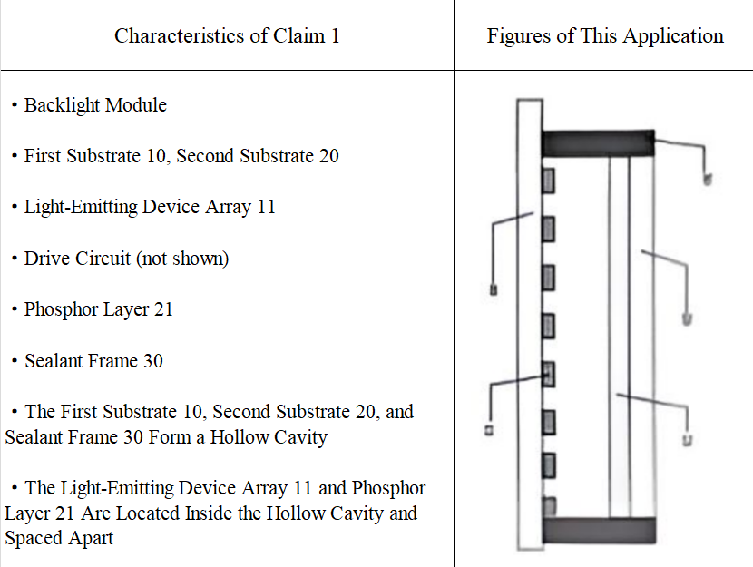
A backlight module, comprising: a first substrate and a second substrate disposed oppositely, an array of light emitting devices on the first substrate, a driving circuit for driving the light emitting devices to emit light, and a phosphor layer being coated on a side of the second substrate facing the first substrate, and a sealant frame sealingly closing and connecting the boundary between the first substrate and the second substrate;
wherein, the first substrate, the second substrate and the sealant frame constitute a hollow cavity, and the array of light emitting devices and the phosphor layer located in the hollow cavity are spaced apart.
Table 1---- Claim 1 of the application
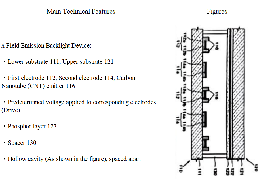
Reference Document 1(CN1637511A)discloses a field emission backlight unit, method of driving the backlight unit, and method of manufacturing lower panel with the following technical features: a lower substrate 111, an upper substrate 121, first electrodes 112, second electrodes 114, carbon nanotubes (CNT) emitters 116, applying predetermined voltages to electrodes respectively (driving), a fluorescent layer 123, a spacer 130 and so on.
Table 2---- Reference Document 1
(3) Summary of examination comments
Substantive Examination stage
Based on this understanding, the substantive examiner made a feature comparison, and considered that Reference Document 1 discloses the fluorescent layer and its related settings. The only difference is that the invention application includes a driving circuit for driving the light emitting device to emit light, sealant frame between the first substrate and the second substrate.
Based on the above difference, the technical problem actually solved by the invention is how to properly design a backlight unit according to needs.
With regard to the above difference, it is easily conceivable for those skilled in the art to provide a driving circuit for driving the light emitting devices to enable the light emitting devices to emit light, and to provide a sealant frame between the first substrate and the second substrate, and the effect of which can be anticipated.
Therefore, it was concluded that claim 1 doesn’t possess inventiveness.
Reexamination stage
In the reexamination stage, the reexamination panel made a deeper and more complete understanding of this application and the reference document 1.
Table 3---- reexamination panel’s understanding of the application
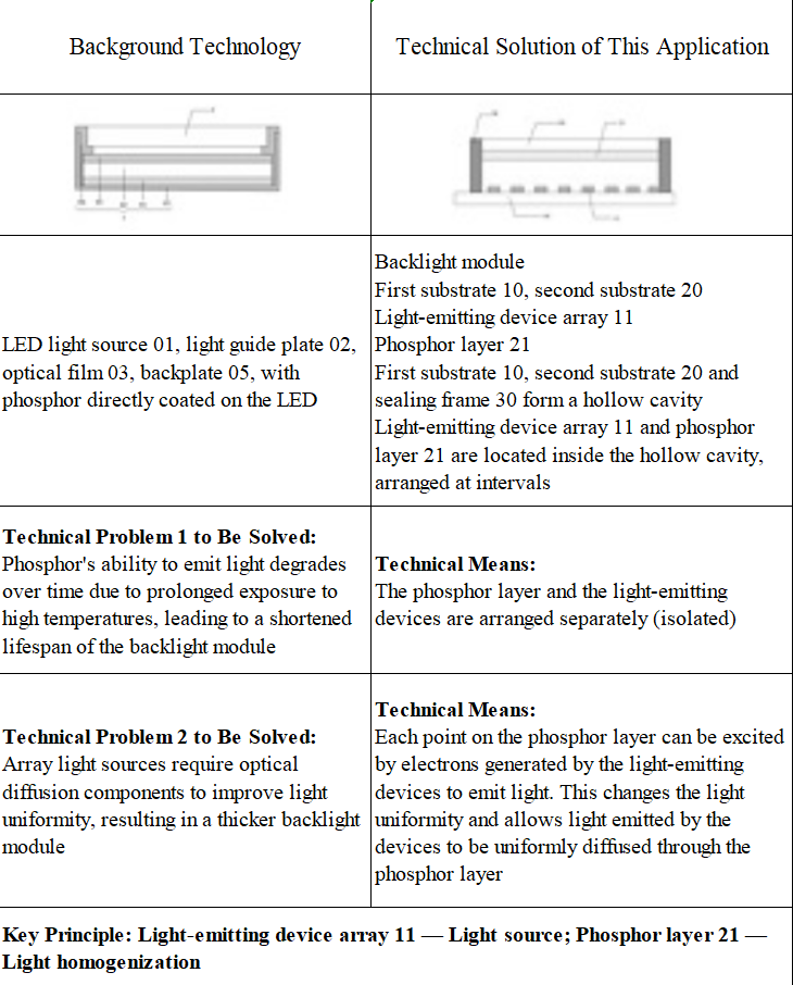
It can be seen from a reexamination panel’s re-understanding of application that the essential technical solution claimed in the application is an improvement on a conventional line light source and a point light source such as an array of light emitting devices, which uses an array of light emitting devices to emit photons to emit light and excite the phosphor layer to illuminate, so as to achieve uniform light effect, that is, even without the phosphor layer, the backlight module of the invention can emit light, and the function of phosphor layer is only improving the luminous effect and simplifying the structure by cooperating with the light-emitting device capable of emitting light. Briefly, the key principle of the application is that an array of light emitting devices 11 is a light source for light emission, and the phosphor layer 21 is for uniforming light.
Table 4---- reexamination panel’s understanding of Reference Document 1
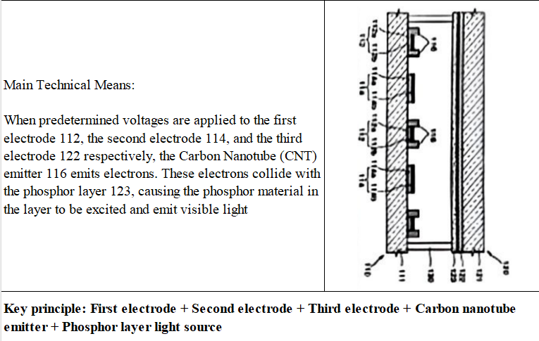
As is fully understood from the reference document 1, the fluorescent layer 123 in the reference document 1 is a constituent part of the light emitting devices, which cooperates with the first electrodes 112, the second electrodes 114, the third electrodes 122 and the carbon nanotubes (CNT) emitters 116 to illuminate, that is to say, they constitute the light source in the technical solution of the reference document 1.
As a result, it can be seen that although "fluorescent/phosphor layer" are recorded in both this application and reference document, the effect of fluorescent/phosphor layer as a different component of the backlight module leads to a different function due to different light-emitting principle. In the application, the phosphor layer is a light-uniforming component; however, in the reference document 1, it is a light-emitting component, and they cannot be regarded as the same or equivalent components as a whole. Therefore, as a whole, reference document 1 does not objectively disclose the phosphor layer and its corresponding arrangement in the application.
On the basis of this understanding, the reexamination panel asserts that: "The difference between claim 1 and the reference document 1 is that the phosphor layer of the application is coated on the second substrate, and the first substrate is provided with an array of light-emitting devices, and the driving circuit is to drive the light-emitting device to emit light, and the phosphor layer is spaced apart from the array of light-emitting devices, and the array of light emitting devices and the phosphor layer are located in the hollow cavity constituted by the first substrate, the second substrate and the sealant frame, and are spaced apart.” That is, reference document 1 does not disclose the phosphor layer and its corresponding arrangement of the application. Thereby, it is considered that the person skilled in the art has no motivation to change the principle of the field emission backlight of the reference document 1 and replace the light-emitting mechanism of the reference document 1 with the light-emitting structure of the application. That is, those skilled in the art have no motivation to obtain the technical solution involved in the application by combining other the prior technical means with the reference document 1 as starting point.
In the end, the panel made a decision to revoke the rejection decision.
2. Case Comments
The focus of the dispute in this case is: whether the reference document 1 discloses the phosphor layer and its corresponding arrangement of the application. In the substantive examination stage, the examiner of substantive examination just found out the corresponding features in reference document, only noticed that there is a phosphor layer in the reference document 1, and its setting position is similar to the application. In this way, there is no deeper and comprehensive understanding of the technical solution, without thinking the specific role of the feature. The examiner only understood the literary meaning of the text and the drawings, and then made a one-sided judgment. During the reexamination stage, the reexamination panel comprehensively understood both the application and the reference document 1, and then conducted the feature comparison to correctly analyze that the role of the fluorescent layer in the application is not light-emitting but light-uniforming. The phosphor layer in the reference document 1 is a part of the light source, and the role is light-emitting. Based on a more complete and comprehensive understanding of the facts, it can be seen that although both the application and the reference document have fluorescent layers, they play completely different roles. Therefore, a more accurate feature comparison was made, and on this basis, a more accurate judgment whether it has inventiveness was made.
In summary, the focus of this case reflects the common ideas of conducting feature comparison. At the same time, the reexamination panel’s way of making judgment gives us a lot of inspiration and guidance. Feature comparison is a critical step in evaluating the inventive of an invention. To judge whether a feature is disclosed, we should pay attention to not only the feature itself, but also the role of the feature in the overall technical solution. We must, from the perspective of those skilled in the art, ascertain the technical facts, accurately understand the technical solutions claimed in the claims and the disclosure in the closest prior art, and correctly identify the distinguishing feature therebetween. Only thinking as those skilled in the art, understanding the technical essence of the invention, and correctly interpreting the claims can lay a solid foundation for the subsequent substantive examination of inventiveness.